Roof Diaphragm Unit Shear
Https Www Woodworks Org Wp Content Uploads Tx Wind Workshops Hour 3 Shearwalls And Diaphragms Pdf

Can A Wood Sheathed Diaphragm Be Classified As A Rigid Diaphragm Woodworks
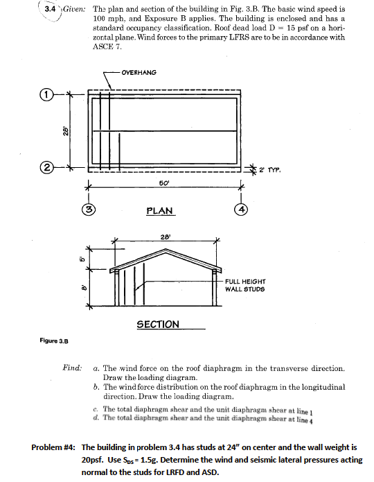
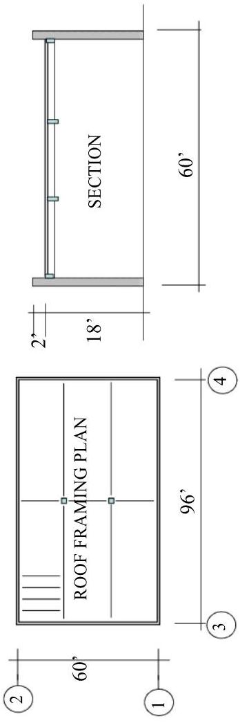
Solved 3 4 Given The Plan And Section Of The Building Chegg Com
Https Www Awc Org Pdf Education Des Awc Des431 Demystifyingdiaphragmdesign 190711 Color Pdf
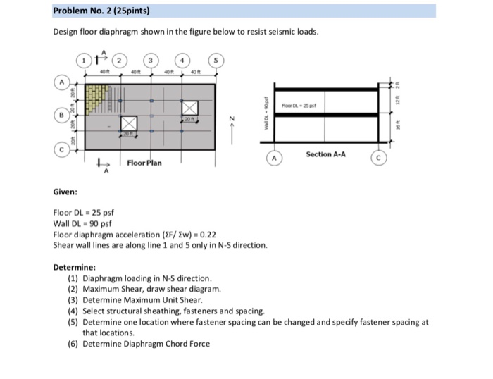
Design Wall Shown On The Figure Below To Resist Se Chegg Com

Structural Design Of Lateral Resistance To Wind And Earthquake For The Home Inspector Internachi
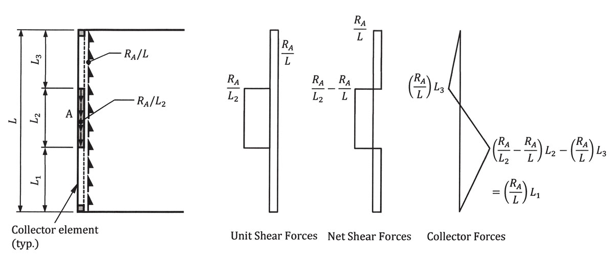
The new or enhanced chord member must be anchored into the diaphragm for unit shear transfer.
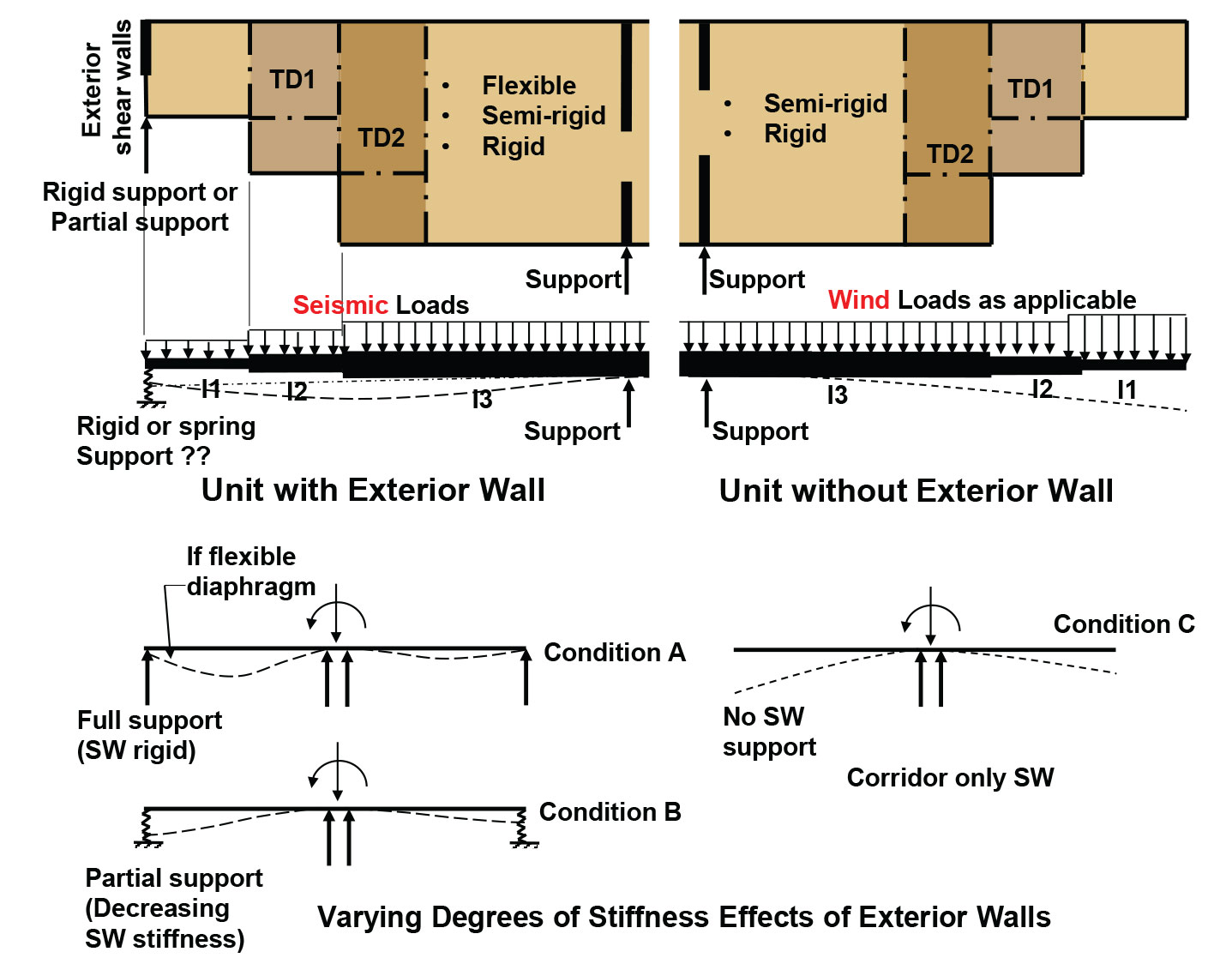
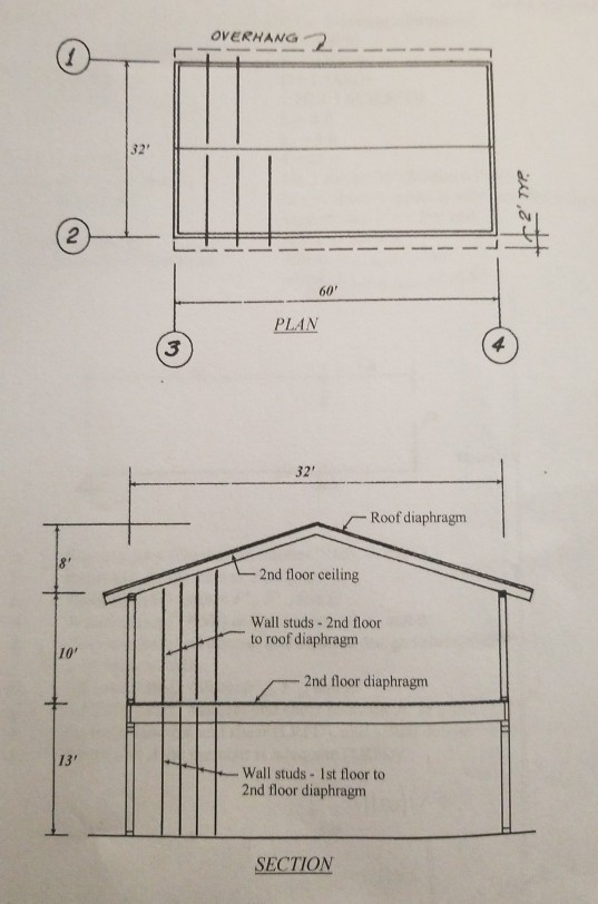
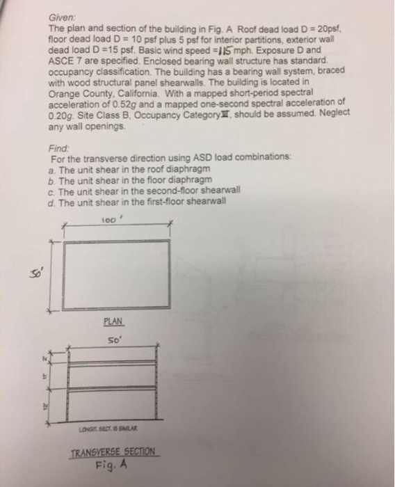
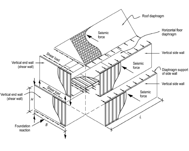
Roof diaphragm unit shear. A shear wall however is a vertical cantilevered diaphragm. The diaphragm resists the in plane loads by acting as a large horizontal beam spanning between the supporting end walls that are known as shear walls. From floor diaphragm to shear. These construction systems can be used when designing a building for lateral loads such as those generated by wind or earthquakes.
At the roof level these wall reactions turn the load in the roof system in the plane of the roof. A diaphragm is a flat structural unit acting like a deep thin beam. Blocked diaphragm all panel edges are supported by and nailed to framing member unblocked diaphragm only the short 4 ft edge is supported by framing member. A shear wall however is a vertical cantilevered diaphragm.
Af pa sdpws shall be met and wood structural panel diaphragms are permitted to resist horizontal forces using the allowable shear capacities set forth in table 2306 2 1 1 or 2306 2 1 2. Diaphragm apparent shear stiffness ga 14 kips in. A diaphragm is a flat structural unit acting like a deep thin beam. Shear nailing of the roof diaphragm north south the diaphragm loaded in the north south direction has been selected to illustrate the design of a wood structural panel roof diaphragm.
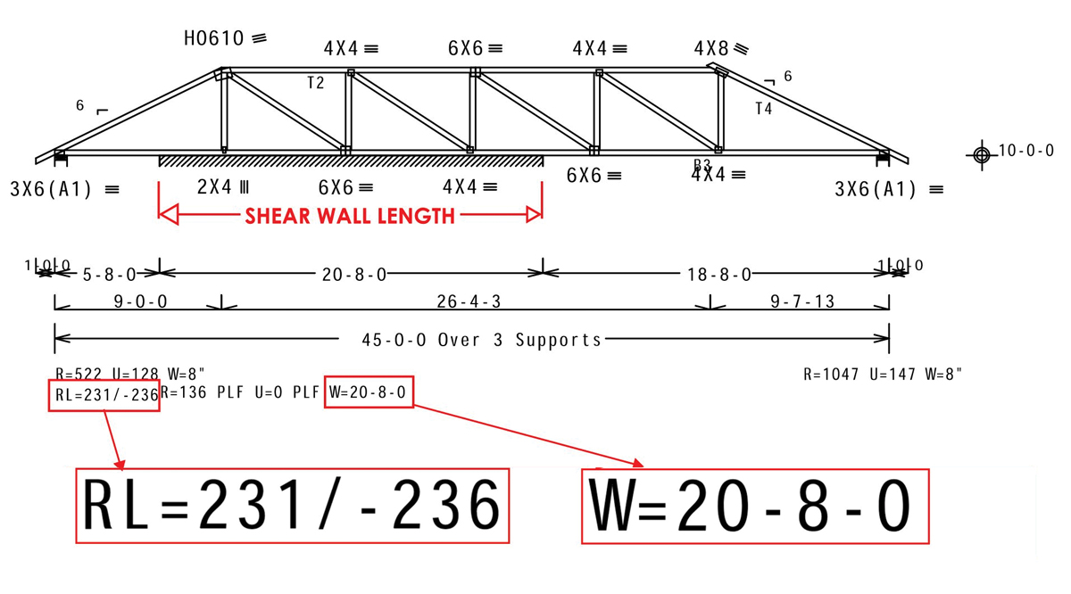
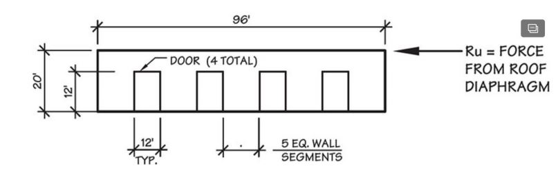
The term diaphragm is usually applied to roofs and floors. Shear diaphragms are essentially planar structural systems found in roofs floors and walls of buildings. This is the most common situation. Max shear diaphragm reaction at shearwall diaphragm unit shear reaction length of diaphragm plf.
Diaphragm unit shear at the east side of line 3 and at line 9 is 136 000 160 850. This horizontal element is known as the diaphragm. Fastening of the chord or chord enhancement should not inhibit this slip. The major components of a diaphragm include the individual deck panels the structural members to which they are connected and the connecting devices or fasteners.
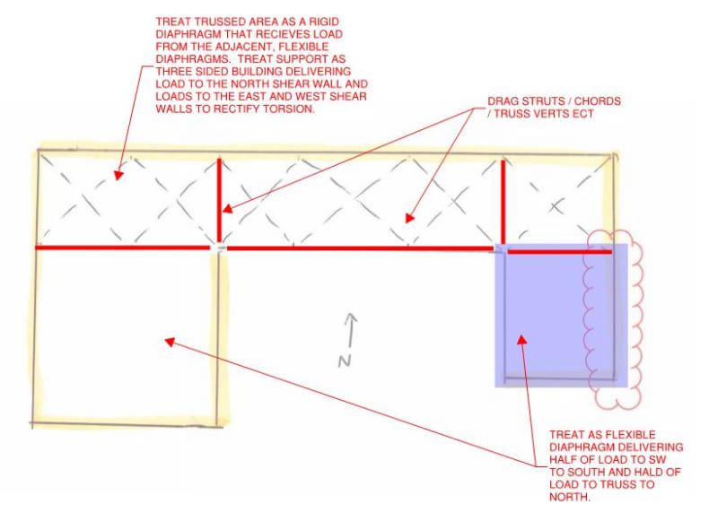
Drag strut at the edge of the diaphragm it distributed the shear force from one diaphragm to another e g. Sdpws table 4 2a diaphragm allowable unit shear capacity for seismic v s asd 255 plf sdpws table 4 2a. The allowable shear capacities in tables 2306 2 1 1 and 2306 2 1 2 are permitted to be increased 40 percent for wind design. Anchorage for shear transfer is also discussed in section 22 2 3.
As a wood sheathed diaphragm is loaded slip will occur between the perimeter framing member and the sheathing. A diaphragm structure results when a series of such vertical and horizontal diaphragms are properly tied together to form a structural unit.
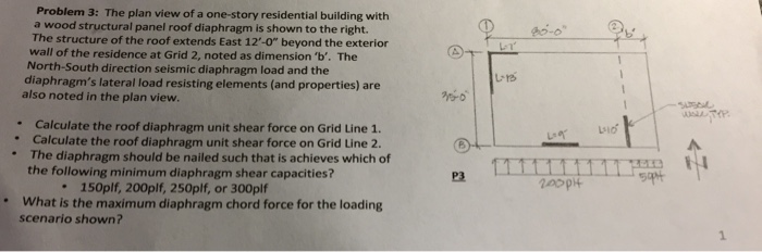
Solved Problem 3 The Plan View Of A One Story Residentia Chegg Com
How Do You Distribute Seismic Diaphragm Force Structural Engineering General Discussion Eng Tips
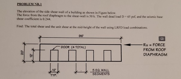
Problem Nr 1 The Elevation Of The Side Shear Wall Chegg Com
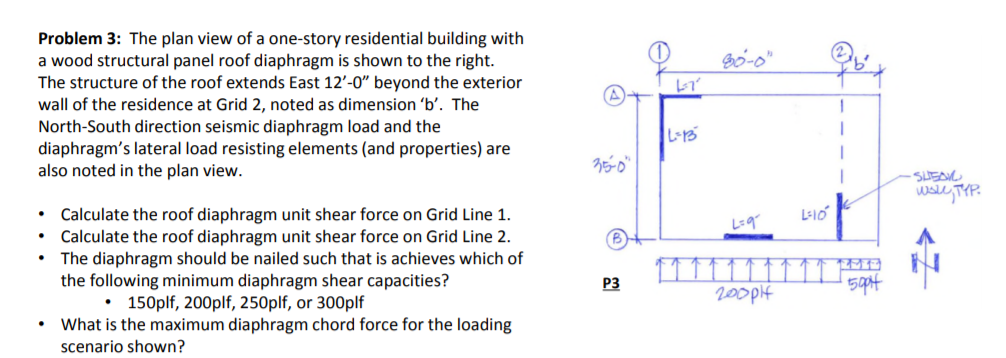
Problem 3 The Plan View Of A One Story Residentia Chegg Com
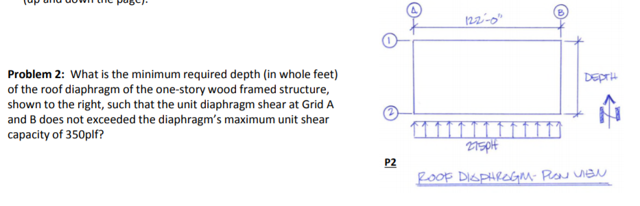
Solved A O Problem 2 What Is The Minimum Required Dept Chegg Com
Structure Magazine Design Of Reinforced Concrete Diaphragms For Wind
Pfhn Fbfymrynm
Https Www Woodworks Org Wp Content Uploads 16ws05 Chicago Wind Workshops Hour 3 Shearwalls And Diaphragms Pdf
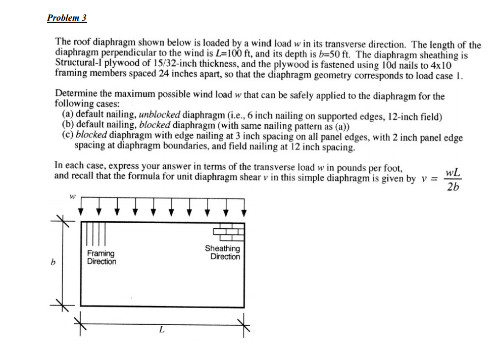
Problem 3 The Roof Diaphragm Shown Below Is Loaded Chegg Com

Horizontal Diaphragms Ppt Video Online Download
Structure Magazine Drag Trusses
The Elevation Of The Side Shear Wall Of A Building Chegg Com
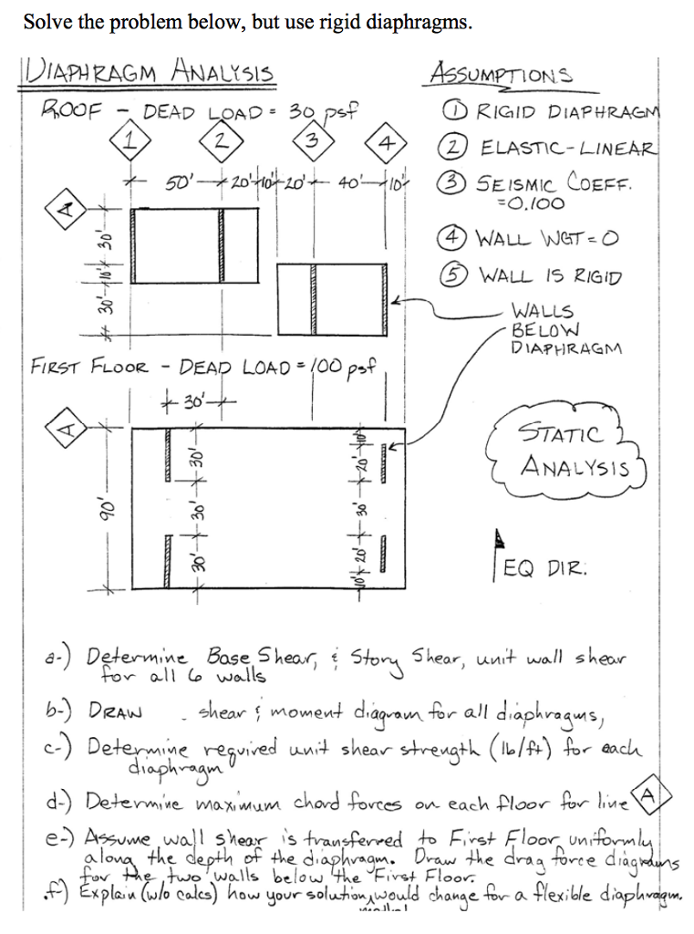
Solve The Problem Below But Use Rigid Diaphragms Chegg Com
Https Www Awc Org Pdf Education Des Awc Des413 1 Shearwallexamples 1hr 140822 Pdf
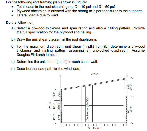
For The Following Roof Framing Plan Shown In Figur Chegg Com
Structure Magazine 5 Over 2 Podium Design
Oe2potnts Given The Plan And Section Of The Two Chegg Com
3 19 Repeat Prob 3 18 Except That Lrfd Load Combi Chegg Com
Https Encrypted Tbn0 Gstatic Com Images Q Tbn 3aand9gcrbpxrliwdewnrquce0kslscyt Mrjx7eok0wks7fl1hje59mn7 Usqp Cau
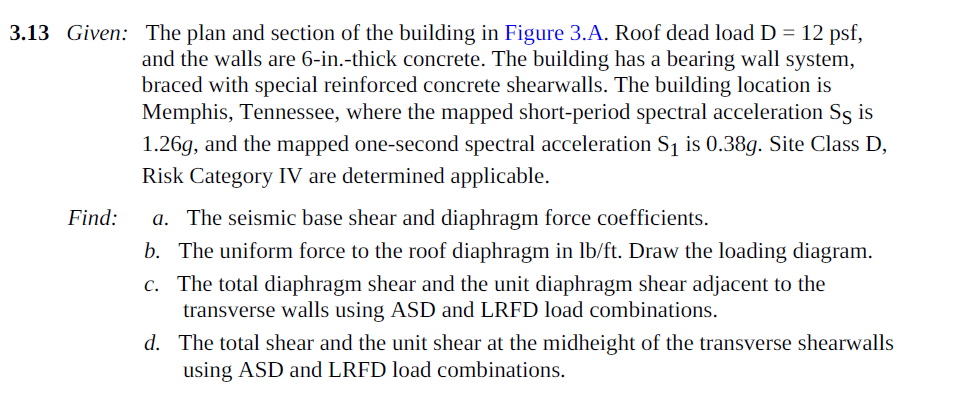
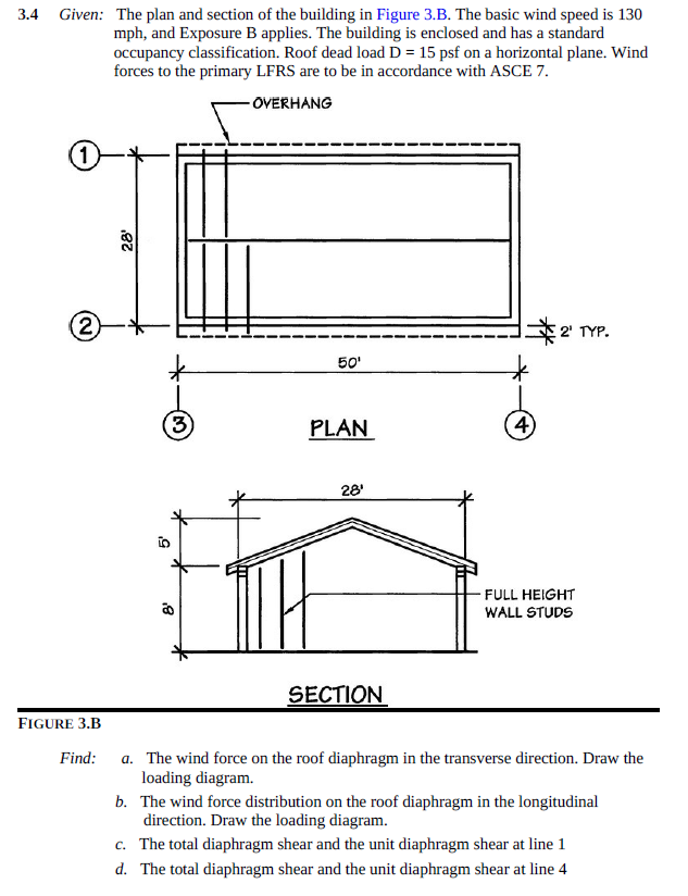
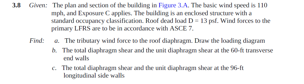
Given The Plan And Section Of The Building In Fig Chegg Com

Inelastic Response Of Steel Roof Deck Diaphragms With Nailed And Welded Connections Sciencedirect
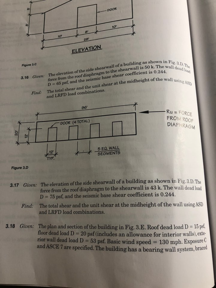
The Elevation Of The Side Shear Wall Of A Building Chegg Com

Analysis Of Irregular Shaped Diaphragms Civil Structural Engineer Magazine

Appropriate Overstrength Of Shear Reinforcement In Precast Concrete Diaphragms Journal Of Structural Engineering Vol 133 No 11
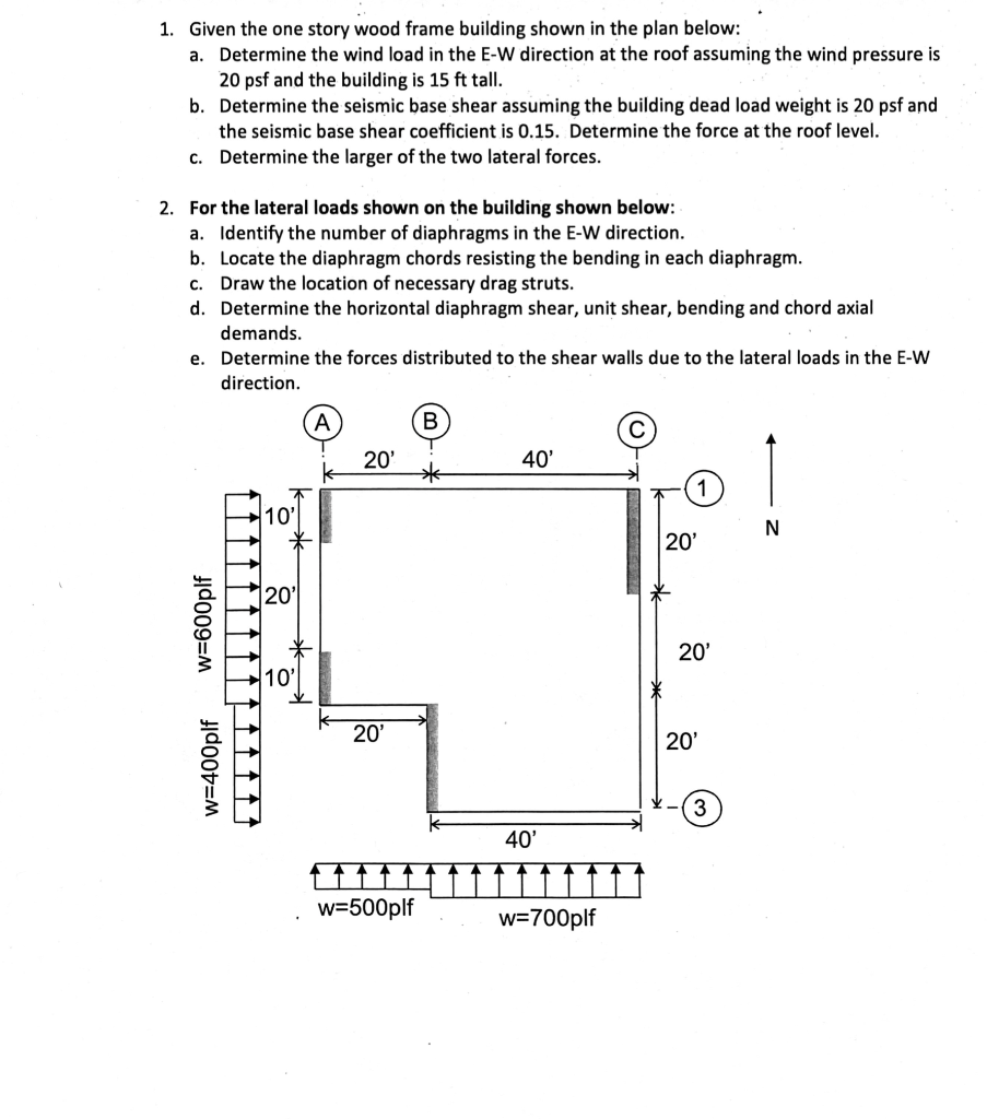
1 Given The One Story Wood Frame Building Shown I Chegg Com
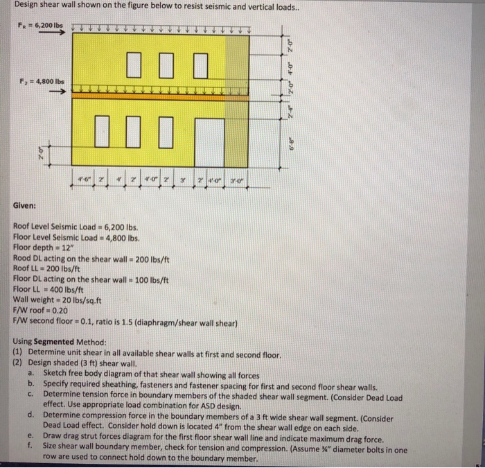
Design Shear Wall Shown On The Figure Below To Res Chegg Com
P3 1given One Story Building As Shown Roof Dea Chegg Com
Ce Center Designing For Earthquakes

Des430 Segment 4 Of 5 Wood Panelized Roof Diaphragms In Heavy Wall Buildings Youtube
For Problem 3 8 Assume L 1 29and Ps30for Zone A Chegg Com

Shear Walls Archives Simpson Strong Tie Structural Engineering Blog
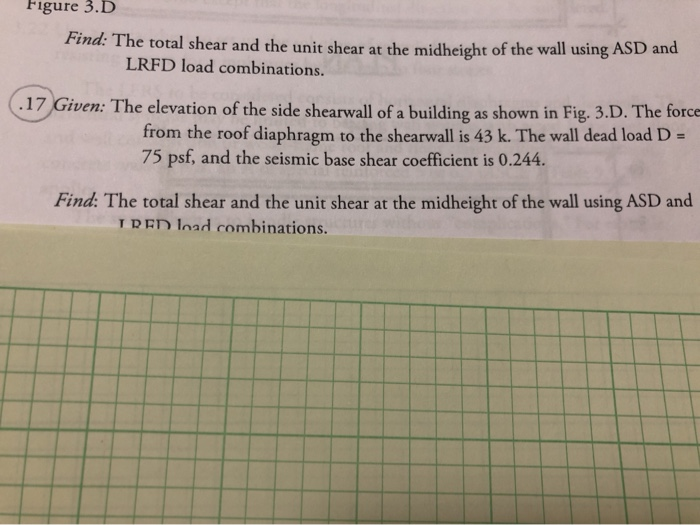
The Elevation Of The Side Shearwall Of A Building Chegg Com
Https Vtechworks Lib Vt Edu Bitstream Handle 10919 78679 O Brien Pe T 2017 Pdf Sequence 1 Isallowed Y
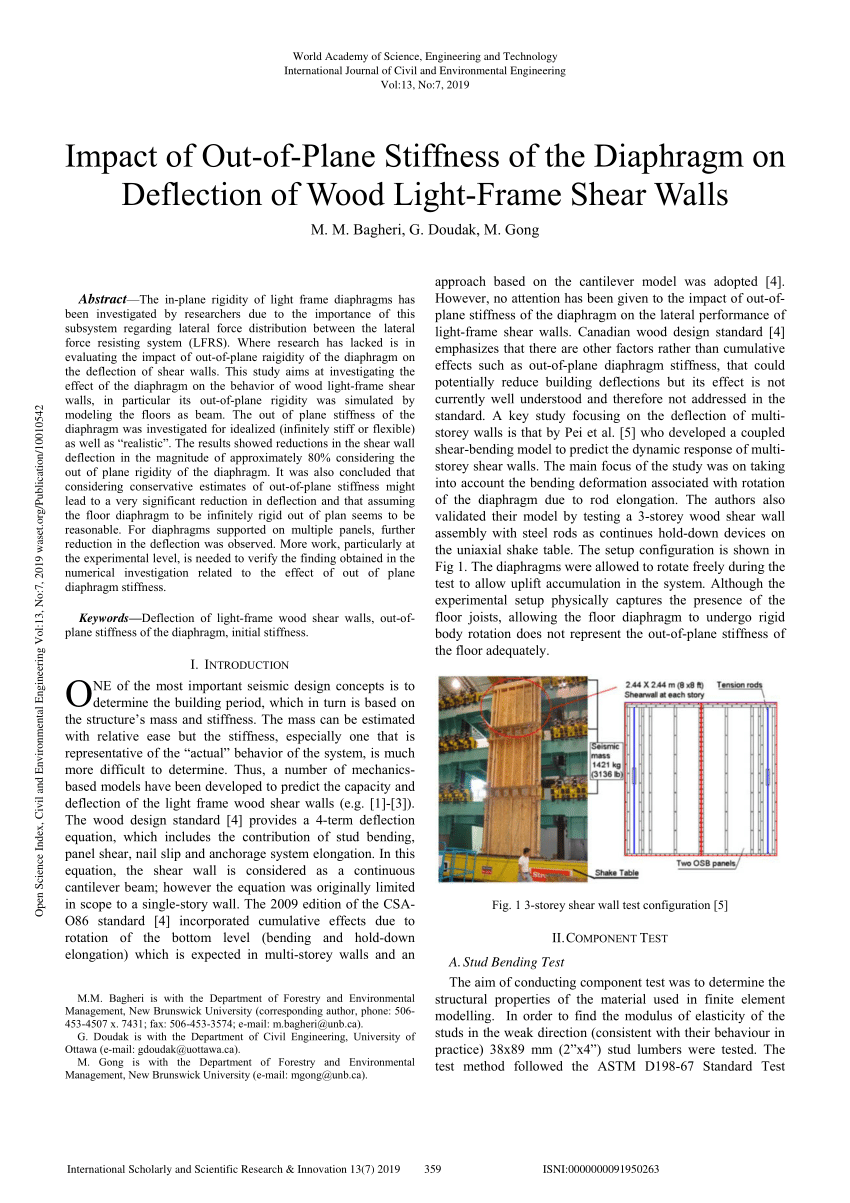
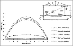
Pdf Impact Of Out Of Plane Stiffness Of The Diaphragm On Deflection Of Light Frame Wood Shear Walls
Https Www Awc Org Pdf Education Std Awc Std401 2 Sdpws2008 Diaphragm 130916 Pdf

Problem Solution
What Is Diaphragm Design Why Is It Important

Wood Shear Wall Software Or Spreadsheets Structural Engineering General Discussion Eng Tips

Pdf Diaphragm Shear Strength And Stiffness Of Aluminum Roof Panel Assemblies
Pdf Beam Spring Model For Timber Diaphragm And Shear Walls
Structure Magazine Seismic Modeling Of An Irregular Water Treatment Structure
What Design And Detailing Considerations Exist When Installing A Layer Of Wood Structural Panels Over A Lumber Deck Diaphragm To Achieve Higher Diaphragm Capacities Woodworks